While I was in that floaty, pre-sleep stage last night, I "saw" the solution. And when I woke up this morning, after the second coffee, I gave it a go.

Those big 5 watt 1k resistors I'd used were overkill. So I replaced them with these 2 watt 1k resistors and slightly altered the layout so that there's now loads of clearance round the input socket. Problem solved. On with the hum fixing.
The heaters in CBA are running AC. And AC heater wiring should be kept electrically balanced! Which is exactly what I hadn't done up to this point. For testing, I was more interested in just making sure the valves warmed up.
With a centre-tapped heater transformer, this balancing can be done by simply connecting the tap to ground somewhere. It doesn't usually matter where, and it's normal practice to connect it to the chassis at the closest point to the transformer.
The transformer I've used doesn't have a centre-tap though, so I had to create an artificial one. There are a couple of ways to do this. I could have just added a pair of 100 ohm resistors, one to each side of the winding, with their ends connected together then down to ground. It's worth remembering that this would add a little to the current draw from the transformer too. With a pair of 100 ohm resistors, this would be another 32mA. Still well within what the transformer can supply. The valves are drawing 900mA and the transformer is good for around 1000mA.
I chose to go the "humdinger" route though. That's just a small preset potentiometer soldered across the heater pins on the pre-amp valve with its wiper connected to the chassis ground.

The advantage of the humdinger is that it can be adjusted to dial out the hum by achieving the right electrical balance. Each of a pair of fixed resistors are never usually quite the same value, whereas by tweaking the preset it's possible to get pretty close to perfect balance.
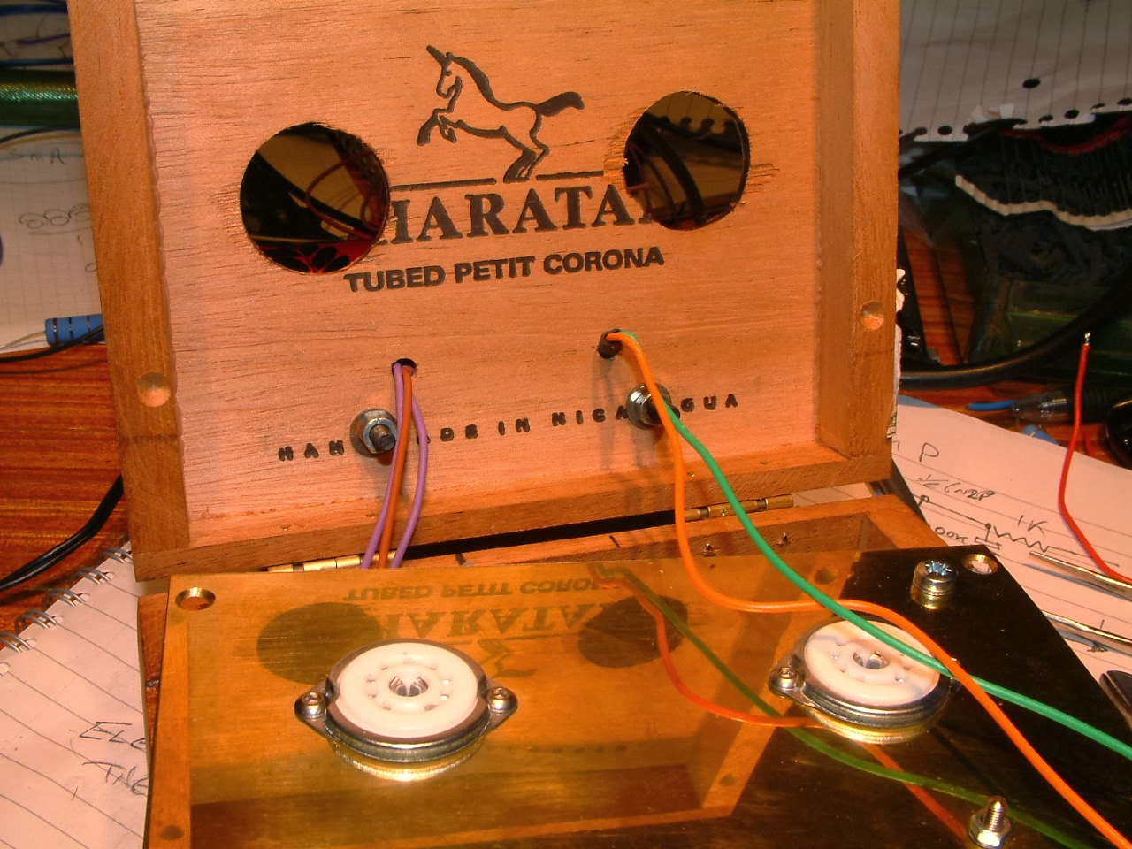
On to the juggling act. I think I'll let the pictures do the talking. It was tight, but not impossible to get the whole thing to come together.


And it was at this point that I remembered I still had to add a speaker socket!


The next few pics are especially for Bob "1B" King. Bob's awesome! He sent me a fabulous shirt all the way from Florida, and in payment I started this blog.
Bob was asking about the RC filtering in the HT supply. Before I screwed the lid down on CBA, I connected my oscilloscope to the different nodes of the supply.
This is straight from the first smoothing capacitor after the bridge rectifier. The scale is 1 volt per centimetre, so we're seeing a ripple of around 3 volts peak to peak sitting on top of the 350 volt supply.

In the next picture, we're still on the same scale and the probe is on the first RC node, the B+1 in my original sketch. We're now looking at just over 1 volt peak to peak ripple.

Next, the B+2 node. Scale now is 0.2 volts per centimetre, and we're seeing probably around .05 volts (50mV) peak to peak.

And B+3 is on the 20mV per centimetre scale, so we seeing around 4mV peak to peak.

Apologies for the slightly blurred image quality. They were taken without flash to bring out the traces and I couldn't be bothered running downstairs for a tripod to grab these pics.
So... it's screwed together and fully working! And I'm delighted with the way it sounds just through a nondescript speaker sat in free air on the bench! It definitely has a growly, bluesy sound. And I think it looks pretty neat too!

Next job is to build a speaker cab to go with it.
Watch this space. :-)
No comments:
Post a Comment