But before we do, here's the disclaimer. It will be repeated more than once during this blog!
Building and modifying amplifiers is DANGEROUS (like most fun things). Valve amplifiers invariably contain both very high voltages and high currents, capable of killing you. Never work on a live amplifier!
This blog is here to share information about a particular amplifier project. It is up to you to exercise caution and common sense at all times to avoid electrocuting yourself, and make your amplifiers safe to use. I am not responsible for your negligence. Building valve amplifiers is also more addictive than nicotine; you have been warned.
My awesome friend, Peter Blind Kiwi Blues Murphy, has built me a CBG (cigar box guitar) called Dirty Creature (named after the Split Enz track). Not only that, but he's delivering it in person at the end of October! Yep. All the way from Australia to Upper Trendleby Down!
By way of payment, I suggested to Peter that we do a trade. His CBG for a one-off, custom Dragondreams valve amp. I also rather foolishly told him that I'd build it into a cigar box, simply so I could use the acronym CBA on one of my amps.
Peter agreed, and work started on the CBA yesterday morning.
Now, with cigar box guitars the rules are simple. Find whatever bits you can and build it. Peter's web site has a wonderful section about just that, so I'm not going to repeat it here. So I decided to use the same "rule" for this amp, except where electrical safety comes into it.
By the way... clicking on any of the images lets you see them full size.

I particularly wanted to use this box because of the words "TUBED PETIT CORONA" that are burnt into it. It's kind of a silly play on words that I like...
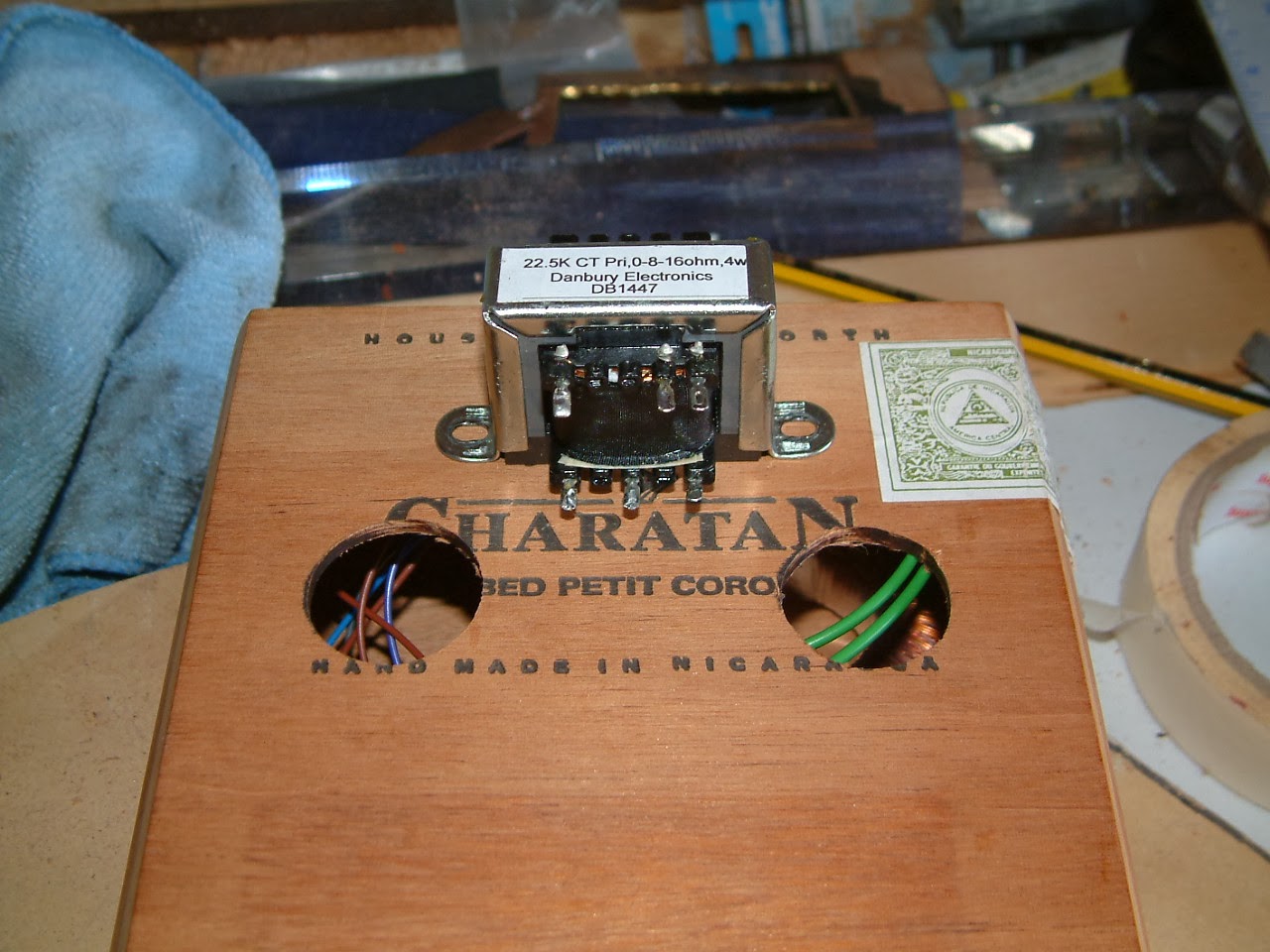
The wires you can see trailing in the pic above are the flying leads for the mains transformer. The internal dimensions of the box are only about 5.5 inches square, so I went for a miniature toroidal transformer from Ampmaker. There are more details about the transformer here, but it has sufficient grunt to power a couple of dual triodes to build a 1 to 2 watt push-pull amp.

As you can see, space is a bit tight. The first thing I decided was that the valve bases and a tag board for the main components would be best mounted to a sheet of brass (simply because I had a strip about the right size) across the inside of the lid of the box with the transformers bolted to the bottom of the box.


My only concern with that approach was the length of the flying leads I'd need from the transformers to the circuit. One of the main causes of instability in valve amps (especially home-brews) is lead dress and where the wires end up. With the lid shut, it'd be impossible to jiggle the wiring about to fix any buzz or oscillation caused by poor cable routing.
So time for plan B.

I figured that it should be possible to build the amp with just enough spare cable to allow me to bolt it all together with the chassis plate running across the top of the base of the box. It might mean a bit of juggling, but it looks do-able. Watch this blog for when the time comes to put this theory into practice!
Having the plate mounted this way means that the valves will have to be removed in order to open the lid. And I don't see that as a disadvantage. If anything, it will probably preserve the valves from accidental damage if the amp needs to be worked on in the future.
I want the lid to close flush, so the plate has to be inset into the box sides to the tune of 0.9mm (that being the thickness of the plate).

I could have dug out a chisel and whittled away at the box, but I'm basically quite lazy. The micro-router attachment on the Dremel could do the same job faster and neater. The only hassle I had was finding a routing jig that would balance across the top of the box. In the end, I used a Telecaster bridge pup routing jig that I was able to twist and turn to get the support I needed. But I forgot to take a pic of that operation.
I was quite pleased with the way that went. And the pics below show what I was trying to achieve (so much easier in pictures than words).


So, I've got the chassis plate to fit the box. What next?
Well... now it's time to make some holes!
The pics below show how I plan the valve bases and the tag board to sit in relation to each other and the edges of the chassis. I don't want the valves too close to each other. The rule of thumb I tend to go by is to space the valves so that there's a minimum of twice their diameter between their envelopes (the glass bits).


This next pic is a gratuitous shot of my anvil (handy for making neat centre-punch marks).

It's a bell former for brass instruments. My uncle bought a music shop that had gone bankrupt and gave me the tools and spares rather than shove them in a skip. This wonderful chunk of metal was among the items.
I used to drill and file the 22mm holes needed for the valve bases when I first started making my own valve amps. I was only ever going to make THE one. Yeah, right. After the third amp I caved in and bought a hole punch.


Best fifteen quid I ever spent on a tool! You might also notice in the pics above that I've marked the plate "top front" with an arrow. It might look silly, but from this point on I'll be working in a couple of dimensions. The valves poke out the top and the tag board will be sat underneath. I'm also going to be marking and drilling four holes at the edges of the plate to screw it to the cigar box... and there's a small problem. The plate isn't quite square (oops). To avoid further issues, the plate is now marked so that it always ends up the right way round when I'm working on it.


So. That's the chassis drilled and punched. Time for a bit of careful measuring so that I can make some holes in the box lid for the valves to poke through.

Which isn't too difficult. I know how far back from the front of the box the plate is going to sit, and I know that it's central across the width of the box. And I have even more wiggle room because I'm going to make the holes in the lid quite a bit larger than the diameter of the valve envelopes. They get HOT and I don't want to set fire to the top of the box.

I used a ZipBit...

...which was probably a bit of a mistake. It snagged a little and made the edges of the holes quite ragged. However, I'd used one that was only a little wider than the valves, so I was always going to have to widen them more anyway. I cleaned the holes up with a sanding drum in the Dremel. Next time (and I'm sure there's going to be more of these amps) I'll use a hole saw.

Now that's the chassis mounted and the holes punched for the valve bases. What's next?
Ah yes. We need some more holes in the box for things like controls and input and output sockets. I also need to drill some holes to mount the transformers.
This amp is a variant of my now infamous "T'Watt". A one watt amp built in response to a friendly challenge when I pointed out that a certain "big name" one watt valve guitar amp wasn't actually a valve amp. This variation of the T'Watt will only have three controls. There's a gain control for the pre-amp stage; a simple treble-cut tone control; and a master volume.
Now the slight worry I had was that these potentiometers had been bought in when all I planned to build were amps with a 1mm aluminium chassis. When I measured the threaded collars, it looked as if they would only just be long enough to poke through the wood on the front of the cigar box. However, there's about another 2mm of unthreaded collar that's a little wider than the threaded bit. By drilling the mounting holes wider, I could get enough clearance to be able to fix the nuts on the pots. If all else had failed, I could buy some pots with longer collars, or counterbore the holes.


In the end, it all went quite smoothly. The pots ended up where I wanted them with plenty of thread poking out to fasten the nuts to. All that remained was to chop down the shafts and to put the chassis plate back in to just double check clearances.

Quite pleased that my measuring worked out. It's hard to spot in this picture, but I was checking that there's clearance between the tag board terminals and the backs of the pots. There is, so I breathed a little easier.
I still have to build the actual electronics yet, but I couldn't resist sticking the knobs on and taking a pic, just to get the "feel" of what the amp's going to look like. It also let me work out the clearance I needed for the input socket. Again though, there was a plan B. If there isn't going to be enough room on the front, it can be mounted in one of the sides.

I'd been waiting for it all the time I was working on the box. The "ah bollocks!" moment. You know, that moment when you realise that things aren't going to go quite the way you envisaged. For me it was the moment when I realised that the output transformer was too tall. It simply wasn't going to fit no matter which way round I turned it.

There's always a plan B. But this time, I couldn't see a plan B. So I went inside to sulk and have another pot of coffee.
I didn't fancy mounting the output transformer on the outside of the box. The main reason for this reluctance was the thought of the 320 volts DC sitting on the HT terminals of the transformer. It kind of makes you shout if you touch it. And it can kind of make you dead too!
But, as you can see, there's plenty of room for it. And on a commercial (expensive) valve hi fi amp, where the transformers are mounted atop the chassis as a matter of course, the high voltage bits are locked away from prying digits by hiding them inside cans.

Isn't it funny how inspiration strikes, often from quite unexpected angles?
Just recently, on one of the amplifier forums I lurk in, someone had been asking about the dimensions of fancy tea tins. They wanted to use them to hide their output transformers! Now I personally can't stand tea. But I'd had a free gift from Whittards in the shape of three sampler tins of espresso coffee... I wonder...

Sure enough, the transformer fits inside the tin! Woohoo! We're back in business. Coffee saves the day once again. All I need to do is drill some holes for the cables and the mounting bolts. And there are benefits to mounting the transformer on the outside anyway. One is that it's better construction practice to get some distance between the mains and output transformers. The other is that the tin will act as an electrical shield once it's grounded through one of the transformer mounting bolts. And third is that having the tin mounted just behind the valves will afford them some physical protection, kind of like a rollover bar on a sports car.

Sure it looks unconventional. But remember the "rule". Build it with what's lying around. And coffee and cigars... c'mon. They go together like lots of things that go together.
The last job of the day was to find out whether Australian audio gear uses IEC C13 connectors - or "kettle leads" as they are somewhat inaccurately known to UK musicians*. Apparently they do, so a suitable socket was chopped into the back of the box.
And that ends this installment of the CBA blog. The next thing I have to do is tidy up my drawings for the physical layout of the circuit, then actually fire up the soldering iron and build the electronics.
Watch this space.


Oh yes, the box it's stood on in the last couple of pics is going to be the speaker cabinet!
* a standard IEC C13 connector won't fit in a kettle!
No comments:
Post a Comment